Aim:
To design a compact HVAC duct system and analyze its airflow behavior and heat transfer performance using ANSYS Fluent, with a focus on optimizing thermal comfort and energy efficiency.
Objectives:
Design an HVAC duct system geometry with realistic flow paths and bifurcations.
Simulate airflow at a velocity of 15 m/s using air as the working fluid.
Perform thermal analysis with inlet air temperature set at 25°C and duct wall temperature maintained at 30°C.
Evaluate velocity profiles, turbulence, and temperature distribution to identify critical zones for improvement.
Methodology:
CAD Modeling:
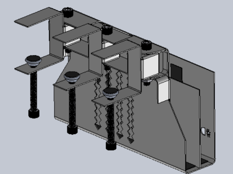
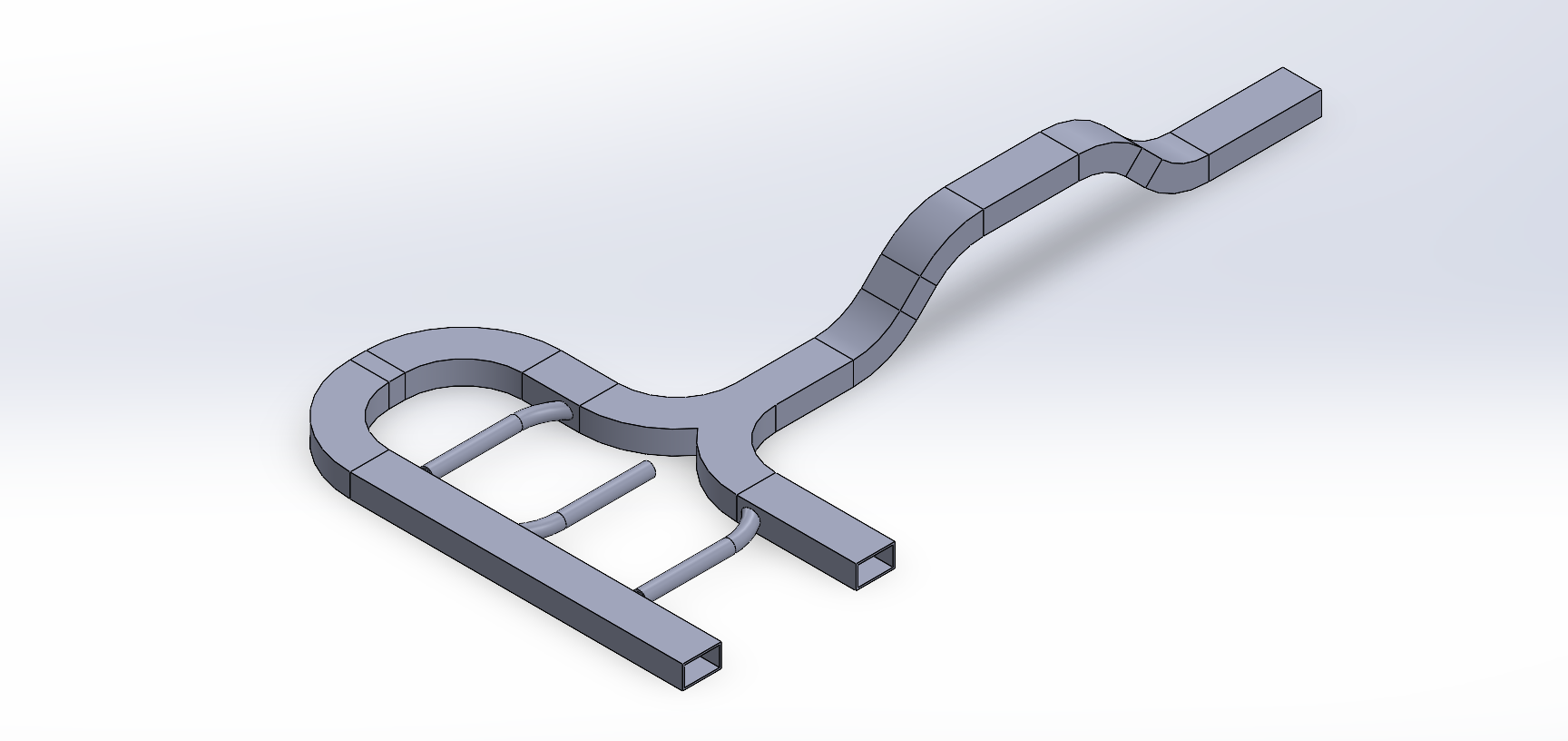
The duct system was modeled in SolidWorks, incorporating vertical and horizontal transitions, multiple bends, and a Y-junction to reflect real-world HVAC flow behavior.
The duct system was modeled in SolidWorks, incorporating vertical and horizontal transitions, multiple bends, and a Y-junction to reflect real-world HVAC flow behavior.
Meshing:
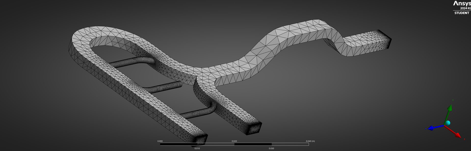
The geometry was meshed in ANSYS Workbench using a combination of tetrahedral and hexahedral elements, refined at the walls and bends to capture boundary layer effects.
The geometry was meshed in ANSYS Workbench using a combination of tetrahedral and hexahedral elements, refined at the walls and bends to capture boundary layer effects.
Simulation Setup (ANSYS Fluent):
Material: Air (ideal gas assumption)
Flow Type: Steady-state, incompressible
Turbulence Model: Realizable k-ε with standard wall functions
Inlet Boundary Condition:
Velocity: 15 m/s
Temperature: 298.15 K (25°C)
Wall Boundary Condition:
Temperature: 303.15 K (30°C)
No-slip condition applied on all duct surfaces
Outlet: Pressure outlet set to atmospheric pressure
Post-Processing:
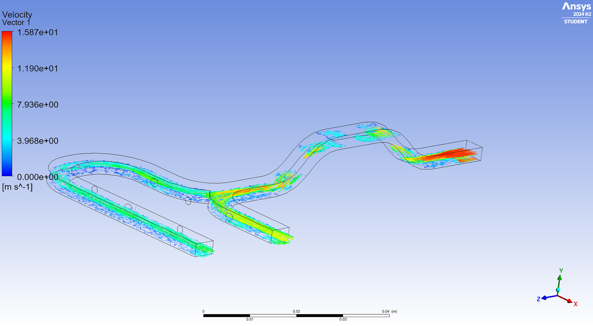
Velocity Vector Plot: Shows flow acceleration at bends and outlet due to directional changes and duct narrowing.
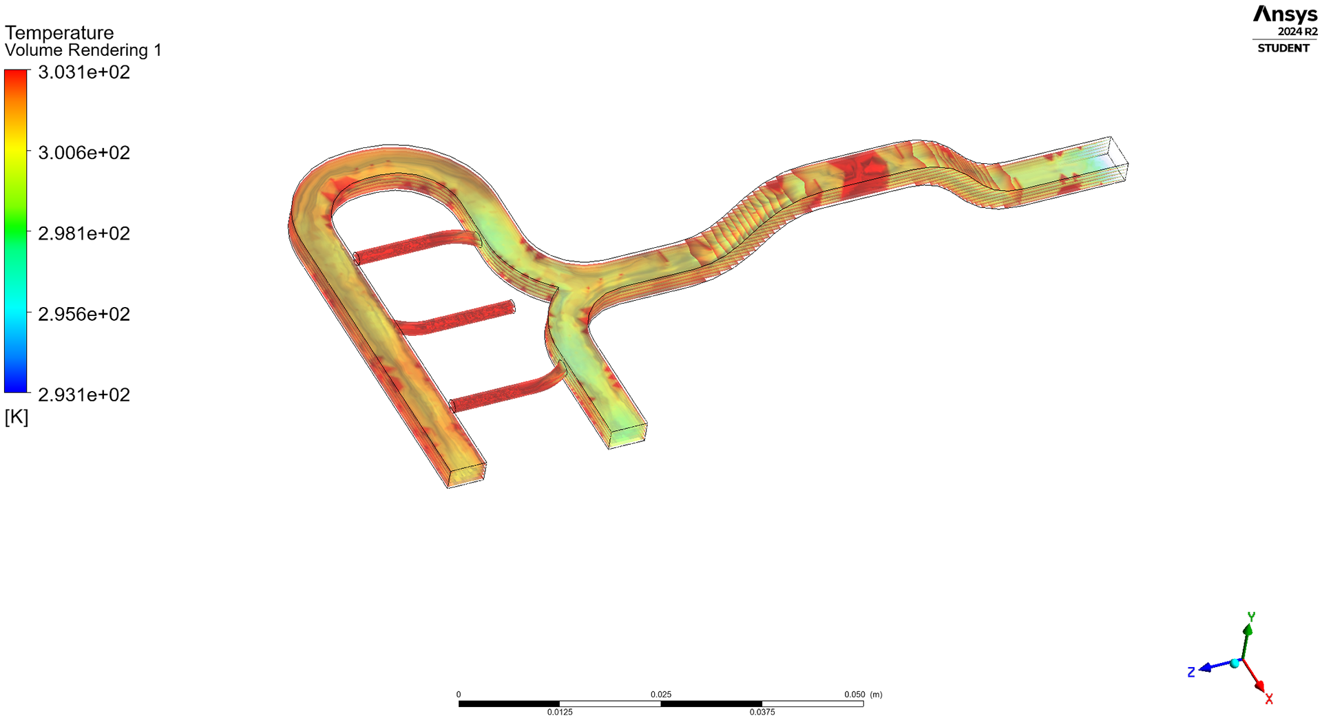
Temperature Volume Rendering: Reveals slight thermal rise in downstream flow regions due to heat exchange from warmer walls.
Results:
The velocity vector visualization (Left image) showed increased turbulence and velocity magnitude in the mid-bend and outlet regions, peaking near 15.87 m/s, indicating localized flow acceleration.
The temperature field (Right Image) demonstrated gradual heat gain from the duct walls, raising outlet temperatures slightly above the 25°C inlet condition.
The flow remained attached along most of the walls, with some minor recirculation at sharp turns, affecting uniform cooling performance.
Challenges Faced:
Mesh refinement trade-offs: Achieving a balance between mesh density and solver time without sacrificing accuracy was critical, especially near complex geometries like bends and junctions.
Thermal convergence issues: Due to small temperature differences (only 5°C), it required careful under-relaxation and convergence controls to ensure stability in coupled heat transfer simulations.
Flow separation: Some unexpected vortices were observed in curved sections, prompting additional turbulence modeling and geometry tweaks.
Future Scope:
Incorporate internal baffles or guide vanes to minimize recirculation and improve flow uniformity.
Extend the study to transient simulations to capture real-time HVAC performance under varying conditions.
Introduce particle tracking or pollutant dispersion models to evaluate air quality impact.
Optimize duct design using topology optimization or parametric studies for energy-efficient airflow and thermal management.
Tools Used:
SolidWorks 2024 – 3D CAD modeling
ANSYS Fluent 2024 R2 (Student) – CFD and heat transfer analysis
ANSYS CFD-Post – Visualization and result interpretation